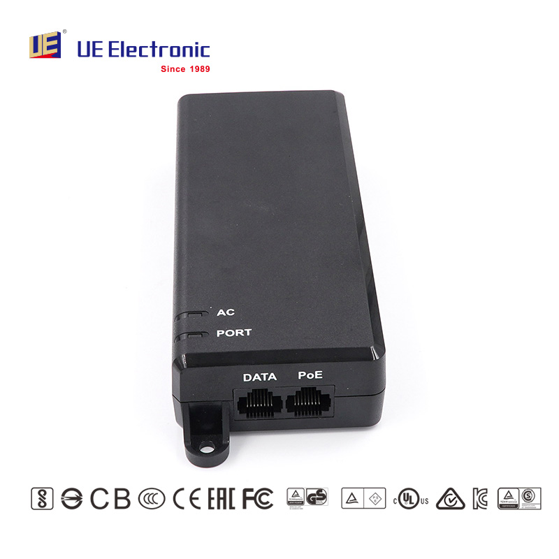
Upgrading network infrastructure using PoE Injectors eliminates the need for expensive dedicated switches. However, selecting the wrong wattage introduces hidden vulnerabilities to your system. Underpowering causes intermittent endpoint reboots and sudden data loss. Meanwhile, overriding negotiation protocols using non-standard power bricks risks frying your legacy equipment. You need the right balance to keep operations stable.
This guide breaks down exact wattage requirements, IEEE standards, and physical layer risks. It helps IT buyers specify the correct power sourcing equipment for enterprise, industrial, and IoT deployments. You will learn how to match standard requirements, account for cable dissipation, and choose between active and passive negotiation strategies. Getting these details right ensures your infrastructure runs efficiently and safely.
Key Takeaways
Match the PoE injector’s IEEE 802.3 standard (af/at/bt) to the Powered Device (PD) to ensure safe handshake negotiation.
Account for cable power dissipation: Power Sourcing Equipment (PSE) wattage is always higher than the actual power delivered to the endpoint at 100 meters.
Standard endpoints (VoIP, basic IP cameras) require up to 30W, while advanced IoT and heavy PTZ setups demand 60W to 90W architectures.
Prioritize "Active" over "Passive" injectors to protect hardware from unnegotiated power surges.
The Hidden Costs of Incorrect Power Provisioning
Mismatched power sourcing equipment severely impacts business operations. Network reliability drops when endpoints fail to draw sufficient current. Administrators often waste phantom troubleshooting hours diagnosing software glitches or network loops. In reality, the physical layer power delivery is failing. Selecting the exact required wattage is non-negotiable for operational continuity.
The Underpowering Risk
Deploying an underpowered injector creates frustrating, intermittent failures. Devices may boot successfully during testing. They often operate fine under standard conditions. However, they fail immediately under peak loads. Consider a Pan-Tilt-Zoom (PTZ) security camera deployed outdoors. It might draw 20W during the day. When night falls, the camera simultaneously activates its mechanical motor and its infrared heater. The power draw spikes to 45W. If connected to a standard 30W injector, the camera drops offline and reboots continually. This phenomenon causes critical data loss during high-security events.
The Overpowering Myth
Many technicians fear plugging a low-power device into a massive 90W injector. They assume the high wattage will overload and destroy the endpoint. This is a myth when dealing with standardized equipment. An active, high-wattage injector relies on standard IEEE handshake protocols. It only delivers the exact power requested by the endpoint. However, opting for passive, proprietary injectors skips this critical safeguard. Passive units force raw voltage down the cable immediately. This action will permanently damage legacy or mismatched equipment.
Common Mistake: Relying on passive power injectors for enterprise environments. Always mandate active negotiation to prevent accidental hardware destruction.
Categorizing PoE Injectors by Wattage and Application
Understanding the tiered IEEE standards helps you match the right hardware to your endpoints. Each standard defines a maximum output at the Power Sourcing Equipment (PSE) and a guaranteed minimum at the Powered Device (PD).
Table 1: IEEE Power over Ethernet Specifications
IEEE Standard
Common Name
PSE Output (Injector)
PD Delivery (Endpoint)
Ideal Applications
802.3af
PoE (Type 1)
15.4W
12.95W
Static IP cameras, VoIP phones, simple access control.
802.3at
PoE+ (Type 2)
30W / 35W
25.5W
Wi-Fi 6 APs, standard PTZ cameras, alarm systems.
802.3bt
PoE++ (Type 3)
60W / 65W
51W
Thin clients, POS systems, video conferencing screens.
802.3bt
PoE++ (Type 4)
90W
71.3W
Smart LED lighting, outdoor enclosures, digital signage.
Standard PoE (802.3af)
The original standard targets low-power network edge devices. These include basic fixed IP cameras, standard VoIP desk phones, and simple RFID access control readers. For these deployments, a standard 15W PoE injector safely delivers up to 12.95W at the device end. It uses two of the four twisted pairs inside the Ethernet cable. This tier remains highly relevant for legacy retrofits and basic office connectivity.
PoE+ (802.3at)
As devices grew more complex, they required more current. The PoE+ standard answers this call. It targets Wi-Fi 6 Access Points, comprehensive alarm systems, and standard PTZ cameras. Deploying a 30W or 35W PoE injector ensures a reliable 25.5W reaches the device. The 35W variant specifically buffers against proprietary vendor overhead and moderate cable dissipation. It keeps high-performance wireless access points broadcasting without throttling radios due to low power.
PoE++ Type 3 (802.3bt)
Type 3 pushes power delivery across all four twisted pairs of the Ethernet cable. It handles intermediate high-power applications. Targets include thin clients, modern point-of-sale (POS) systems, and building management gateways. A 60W or 65W PoE injector provides reliable 4-pair power delivery. It guarantees up to 51W at the device end. This tier is essential for powering multi-radio wireless systems and compact computing edge devices.
PoE++ Type 4 (802.3bt)
The highest current standard drives the modern IoT landscape. It targets smart LED lighting networks, large digital signage displays, and heavy industrial enclosures featuring internal heaters and blowers. A 90W PoE injector offers the maximum standard power currently available. It guarantees 71.3W at the device end across 100 meters. Leveraging this tier future-proofs your smart building rollouts against increasing power demands.
Essential Evaluation Criteria Beyond Output Power
Raw power output only solves half the equation. Network administrators must evaluate the underlying intelligence, speed, and physical build of the injector. Missing these criteria leads to bottlenecks and safety hazards.
Active vs. Passive Negotiation
Enterprise environments must strictly mandate active injectors. Active IEEE-compliant injectors perform a safety handshake before delivering full power. They send a low-voltage pulse down the line. They look for a specific 25k-ohm signature resistance from the endpoint. If the signature matches, the injector categorizes the device and delivers the appropriate wattage. If the signature fails or is absent, the injector suppresses the power. This prevents accidentally frying non-PoE computers or legacy switches. Passive models skip this vital step, presenting a severe risk to corporate hardware.
Data Throughput Thresholds
Power is entirely useless if your data encounters a bottleneck. Injectors sit inline between the switch and the endpoint. They must support the required network speeds. Matching the injector’s data rate to your endpoint is critical. A gigabit injector serves most cameras well. However, deploying a Wi-Fi 6 or Wi-Fi 7 Access Point requires multi-gigabit throughput. You must specify 2.5G, 5G, or 10GBASE-T rated injectors for these high-bandwidth devices. Using a 100Mbps or 1G injector on a 10G access point instantly cripples network performance.
Industrial vs. Commercial Build
Location dictates hardware selection. Commercial units belong inside climate-controlled IT closets. Deploying at the true edge requires industrial resilience. You must assess thermal management capabilities. Look for extruded aluminum housings acting as passive heatsinks. Verify DIN-rail mounting capabilities for control panels. Most importantly, ensure the operating temperature ranges span from -40°C to 75°C. Edge deployments in warehouses, factory floors, or outdoor weatherproof enclosures destroy standard commercial injectors rapidly.
Compliance and Safety
Hardware connecting to corporate mains requires stringent safety validation. You must verify UL certification or equivalent regional safety marks. Look for built-in surge protection ratings. Outdoor endpoints act like lightning rods during storms. The injector should isolate the downstream switch from electrical surges. Additionally, ensure the unit features proper EMI/RFI shielding. Unshielded power equipment introduces electromagnetic interference into the data pairs, causing packet loss and jitter.
Implementation Realities: Cable Loss and Thermal Risks
Physical layer physics dictate actual power delivery. What leaves the injector is rarely what arrives at the device. Understanding cable resistance and thermal buildup prevents deployment failures.
The PSE vs. PD Deficit
Voltage drop is an unavoidable reality of copper cabling. The IEEE standard builds a buffer into the specification to account for this deficit. A 90W injector only guarantees approximately 71.3W at the maximum 100-meter run. The remaining wattage dissipates as heat along the cable length due to DC resistance. You must always calculate your power budget based on the Powered Device’s peak consumption, never the PSE’s maximum rating. If your device requires exactly 80W, a standard 90W setup will fail at long distances.
Cabling Requirements
High-wattage deployments strictly require solid copper Cat6 or Cat6a cabling. Pushing 60W or 90W over inferior cabling generates significant physical risks. You must completely avoid Copper-Clad Aluminum (CCA) cables. CCA cables exhibit much higher DC resistance than pure copper. Under high PoE loads, CCA cables experience severe voltage drops. Worse, they present extreme thermal hazards. The aluminum core heats up rapidly under sustained current, risking melted jackets and potential fire hazards.
Best Practice: Always test cable runs using a certifier. Ensure the loop resistance falls well within IEEE parameters before activating high-wattage endpoints.
Heat Dissipation in Bundles
Routing dozens of high-wattage PoE lines together compounds thermal issues. Heat accumulates rapidly in the center of dense cable bundles. This localized heating increases cable resistance further, reducing power delivery and degrading signal integrity. Managing cable bundle sizes is mandatory. Keep bundles small—ideally under 24 cables per bundle for 60W/90W applications. Use cable management techniques allowing airflow between bundles. Proper routing prevents signal degradation and keeps cable jackets from melting over time.
Decision Framework: Shortlisting the Right Injector
Selecting the right equipment requires a systematic approach. Follow these four steps to eliminate guesswork and standardize your hardware rollout.
Step 1: Endpoint Audit. Read the official specification sheet of the Powered Device. Do not just look for the maximum wattage draw. Look for the specific IEEE standard (802.3af, at, or bt). The standard dictates the negotiation method required.
Step 2: Buffer Calculation. Factor in a 15-20% power buffer. This buffer accounts for power loss over long cable runs. It also covers peak start-up draw, especially for devices featuring mechanical motors or boot-up heating elements.
Step 3: Network Speed Mapping. Ensure the injector does not throttle your backhaul data rates. Verify the data pins support the exact bandwidth required by the endpoint.
Step 4: Environment Validation. Select ruggedized or industrial form factors if deploying outside climate-controlled IDF or MDF closets. Verify temperature ratings and mounting mechanisms.
Next Steps
We advise standardizing your enterprise deployments to streamline inventory management. Use 30W/35W units as your default for general office edge devices. This covers phones, standard cameras, and access control seamlessly. Reserve the heavy 60W/90W models strictly for intensive IoT implementations like smart lighting and multi-radio access points. Standardizing reduces confusion and speeds up replacement times during maintenance windows.
Conclusion
Accurate wattage selection bridges the gap between hardware capability and true network stability. Choosing the exact standard prevents frustrating reboots and protects valuable edge devices from power-related damage. Remember the overarching rule: Over-spec the wattage capability using IEEE Active standards to future-proof your network, but never under-spec your cabling quality. High-quality copper is the foundation of reliable power delivery.
Your next step is auditing your upcoming hardware deployments. Review your current endpoint data sheets carefully. Consult supplier technical compatibility matrices to ensure exact matches. If you need more insights into industrial network power solutions, take a moment to learn about us and our engineering standards.
FAQ
Q: Can I use a 90W PoE injector on a 15W device?
A: Yes, provided it is an Active 802.3bt compliant injector. Active units perform a mandatory resistance check before sending power. The injector will auto-negotiate with the endpoint and safely deliver only the required 15W, preventing any hardware overload.
Q: Why does my endpoint specification say 71W but I need a 90W injector?
A: This discrepancy accounts for power dissipation over Ethernet cables. DC resistance converts some electrical energy into heat along the wire. To guarantee 71.3W reaches the endpoint at the maximum 100-meter distance, the injector must output 90W at the source.
Q: What is the difference between a 30W and 35W PoE injector?
A: The difference often reflects marketing terminology or specific vendor overhead allowances. Both generally fall under the standard IEEE 802.3at (PoE+) parameters, designed to ensure a reliable 25.5W delivery at the device end after accounting for cable losses.
Q: Can I plug a PoE injector into a switch that already provides PoE?
A: Yes, but you must configure it correctly. You should log into the switch management interface and disable PoE on that specific port. Alternatively, use a compliant midspan injector safely; it will override the switch's power limits without pushing voltage back into the switch hardware.
UE Electronic is a power supplier integrating R&D, production and sales. We maintain a leading level in extension cord and GaN charger.We are committed to becoming a global power supplier.